E-textiles & Wearables I
Class five - 24 October 2017
Making a slider potentiometer
I have some conductive fabric and some resistive film like velostat and I thought a slider potentiometer would be a nice exercise to start with. I based my project on some experience I made in a workshop during FAB13 with Wendy Neale and Ohad Meyuhas about soft sensors and this documentation I found on Kobakant's pages.
First I tested the system with a Shanghaino (a simple Arduino clone I developed in Shanghai, based on the Fabschoolino from Waag Society) to check that my idea would work. The Conductive fabric strip is connected to an analog pin, while the two ends of the resistive film strip are connected to GND and VCC. Using a connector plated with adhesive copper foil I connect the two strips at different positions, determining a difference in the resistance on the two halves of the resistive film.
This is basically how a normal potentiometer works, you connect 5Volts to 0Volts with two variable resistors and the signal you pick in between the two resistor is called VoltageOut and it can be read by the Atmega's ADC (Analog to Digital Converter) giving you a scale of values between 0 and 1024. It's also the basic principle of a voltage divider.
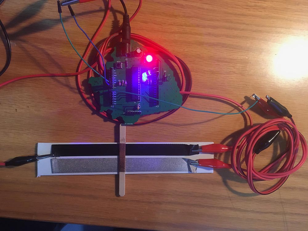
First test with a shanghaino
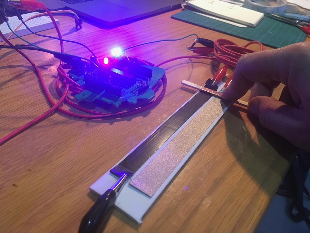
LED at full power (slider at right end)
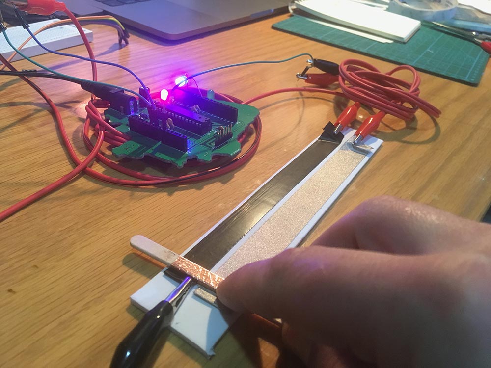
LED at low power (slider at left end)
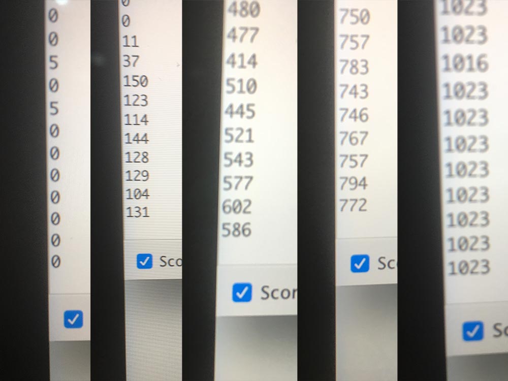
ADC Voltage values in five position of the slider
Programming
The first code I tested was only printing the values on the serial monitor and then I added an LED to change its brightness. Later I switched the LED with an RGB LED and I assigned each one of the eight color achievable to eight location of the slider on the two strips by specifing appropriate values of voltage read by the ADC.
Electronic production
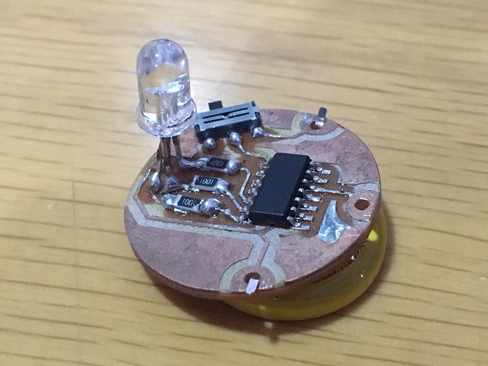
I designed a little board with Eagle and milled it on the Roland SRM-20 milling machine. The circuit uses an Attiny44, an RGB LED with appropriate resistors, an on-off switch and a 3.2Volts button battery.
I programmed the SMD Attitiny inserting it to a spring plug connected to my FabISP and after that I soldered it to the PCB and completed soldering the other components.
I plan to complete this sensor giving it the shape of a bracelet where you can slide the buckle to change the color on your forearm based on which color you prefer to wear, so I called it a MoodBand.

Spring connector for Attiny44
ADC Voltage values in five position of the slider
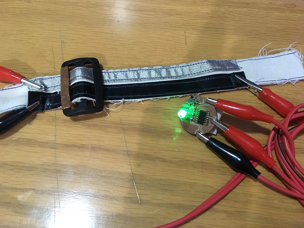
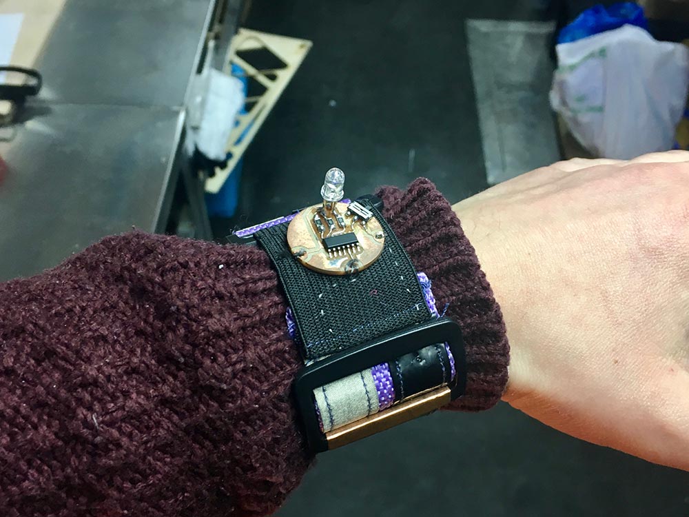
MoodBand displaying one color (don't ask me which color, I'm clorblind!)
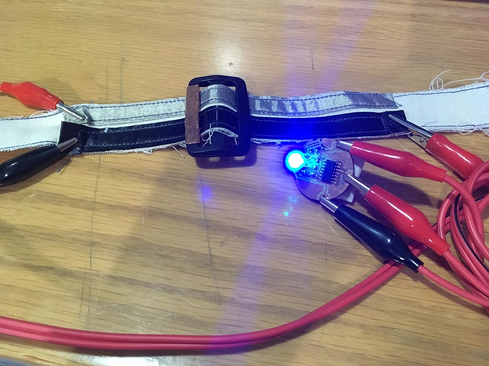
MoodBand displaying another color at different position of the slider (I can only tell it's either Red, Blue, Green, Magenta, Cyan, Yellow, White or Black-Off)

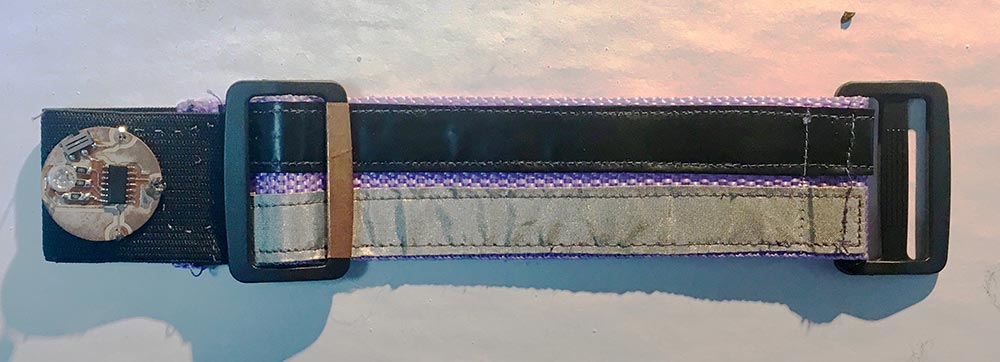
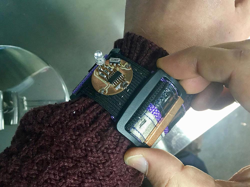
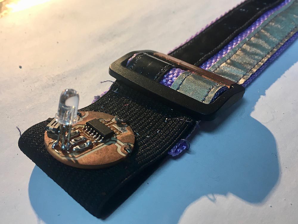
Closer look at MoodBand
Moodband final shape
The following pictures show the Moodband in its final shape, it can be used on your arm just like a watch. Just slide the buckle on the wristband and change the color of your mood... Unofrtunately, these pictures were taken after some time since it's creation, and the LED is not working anymore!
Moodband
Files Storage
This website by Saverio Silli (based on Twitter Bootstrap) and all its content is licensed under the following license: CC Attribution-Share Alike 4.0 International.